

The two Uintahs #50 and # 51 were built by Baldwin for the Uintah railroad in Utah in the '20s. They were the largest and most powerful narrow gauge locomotives ever built with 44,000 lbs. of tractive force.
LGB made several electric models which were very nice but not prototypical in dimensions. Bachman has a 2-6-6-2 which is smilar in looks but is not a Uintah.
Mine will be live steam and to the correct 1:20,3 scale.
![Image]()
Baldwin photo
![Image]()
The full Walschaerts dimensions were ploted out on Dockstader's program available on the web The termilology is generic for all valve systems so the drawing above ties the various parts to the dimension input boxes
As I will be using 5/8" cylinders, it is important that they are as efficient as I can get them so much detail has gone into this design
![Image]()
1" square bar is rounded off on one corner on the router table with a 1/2" rounding over bit . Cuts are done 1/8" at a time at slow speed.
![Image]()
Top shows radius
Here the cylinders are cut to length in the table saw cross cutting jig
![Image]()
The cylinders are cut about .040" oversize and then faced off on the self centering four jaw chuck
![Image]()
Cylinders are bored out. Boring tool is ground from an old end mill
![Image]()
A piece of scrap wood is cut to 45 degrees and used to ser the cylinders in place where they are clamped in.
![Image]()
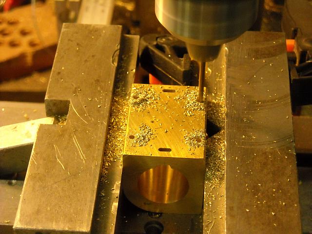
A 1/16" end mill is used here to get a large volume oval port without going too far into the cylinder bore
![Image]()
The port is then finished off on the top of the piston
![Image]()
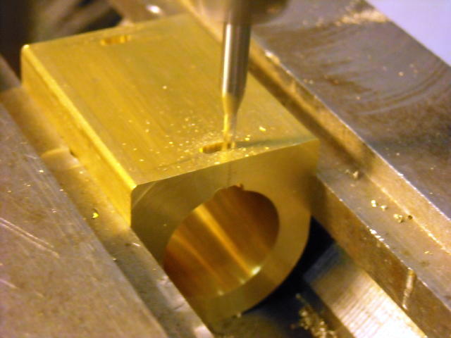
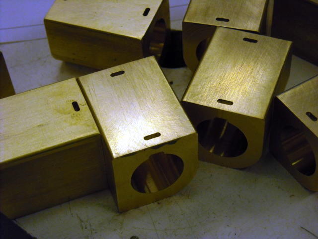
Holes are drilled for mounting the cylinder to the frame and for mounting the valve to the cylinder
![Image]()
LGB made several electric models which were very nice but not prototypical in dimensions. Bachman has a 2-6-6-2 which is smilar in looks but is not a Uintah.
Mine will be live steam and to the correct 1:20,3 scale.
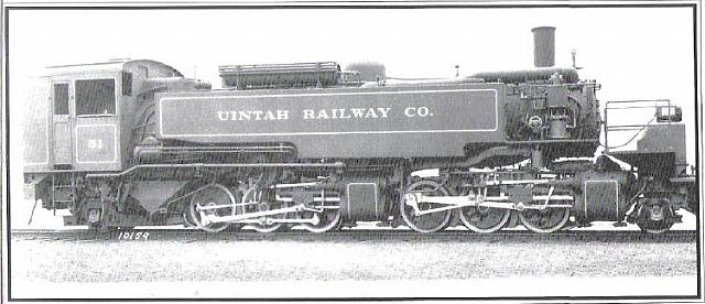
Baldwin photo
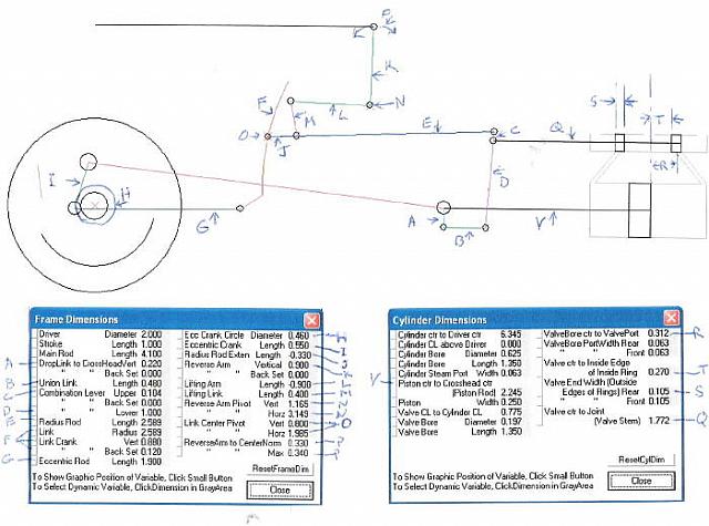
The full Walschaerts dimensions were ploted out on Dockstader's program available on the web The termilology is generic for all valve systems so the drawing above ties the various parts to the dimension input boxes
As I will be using 5/8" cylinders, it is important that they are as efficient as I can get them so much detail has gone into this design
- www.billp.org//ValveGear.htm
The cylinder and valve design is different from most. As I will be using piston valves, I will be able to have all of the porting in the valve body (per the original) this makes the valve assembly fully contained and attached to the cylinder with four screws. This makes the cylinder simpler and less massive.
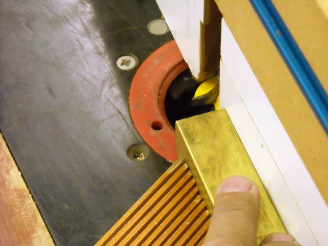
1" square bar is rounded off on one corner on the router table with a 1/2" rounding over bit . Cuts are done 1/8" at a time at slow speed.
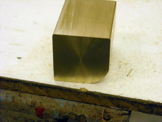
Top shows radius
Here the cylinders are cut to length in the table saw cross cutting jig
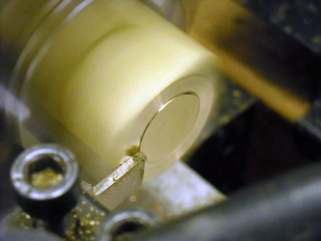
The cylinders are cut about .040" oversize and then faced off on the self centering four jaw chuck
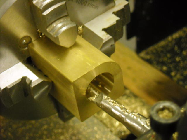
Cylinders are bored out. Boring tool is ground from an old end mill
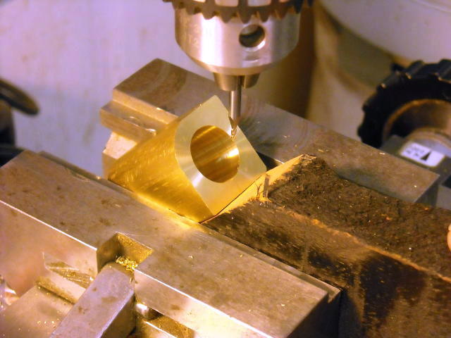
A piece of scrap wood is cut to 45 degrees and used to ser the cylinders in place where they are clamped in.

A 1/16" end mill is used here to get a large volume oval port without going too far into the cylinder bore
The port is then finished off on the top of the piston
Holes are drilled for mounting the cylinder to the frame and for mounting the valve to the cylinder


")


