G Scale Model Train Forum banner

Drag/Inertia Car

1 reading
17K views 29 replies 16 participants last post by  Darrene  
#1 · (Edited)
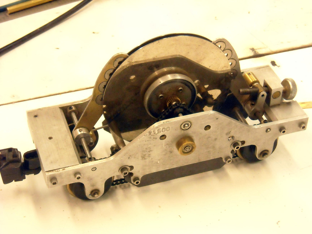
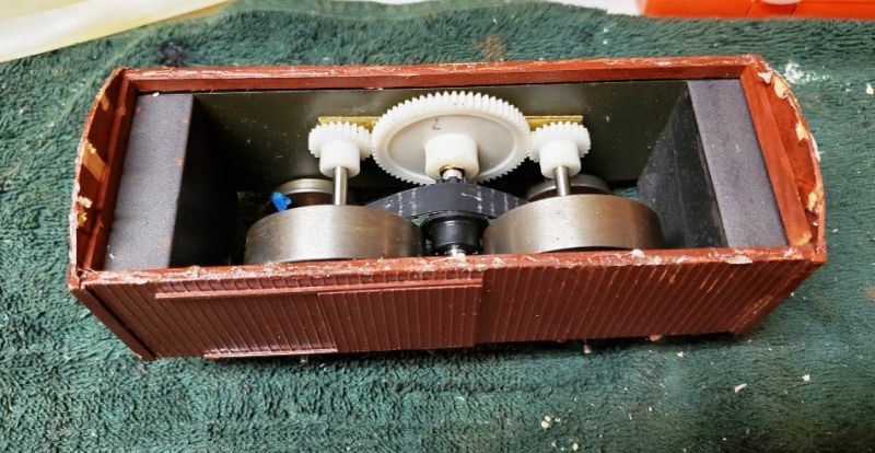
This little beast turned up today, from Peter K's estate. It's essentially a flywheel car that makes a live steam loco work harder to accelerate or slow down, thus simulating the interia of a real train.

Image


Image


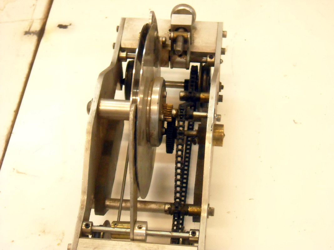
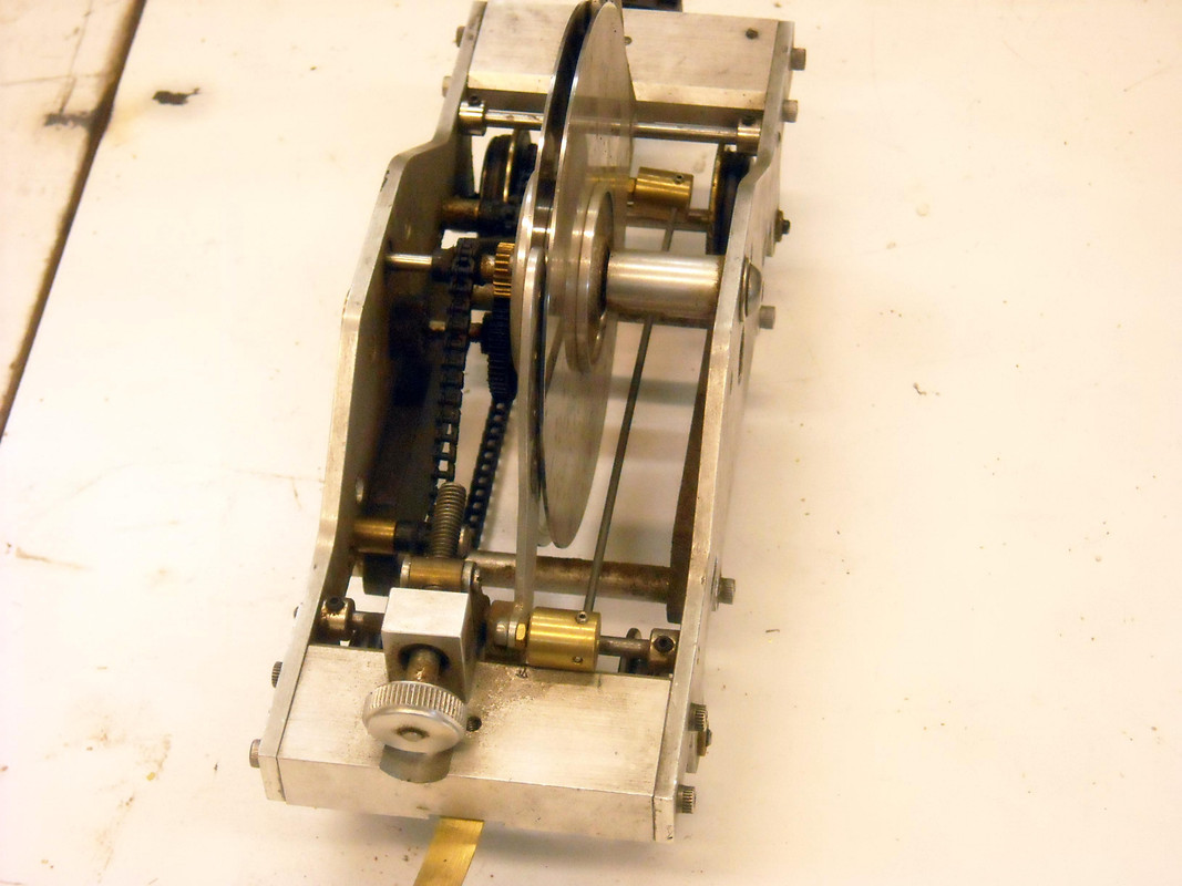
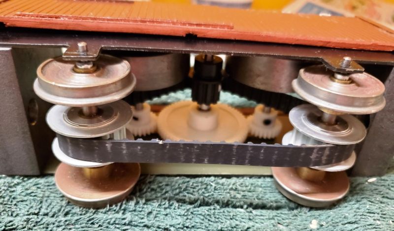
Those look like solid steel flywheels and the ends of the 'box' are solid cast iron. The thing weighs a ton - intentionally to make sure the wheels grip and it doesn't just get dragged. One flywheel was disconnected (the gear was moved on the shaft so it didn't get driven.) That may be a way of making it work with only 1/2 the inertia!

I have no idea who made it but it is a nice job. I will be taking it to Jerry's SC&M to see if (a) his track can handle the weight and (b) whether it works. I have a little english train of Thomas stuff with a 'Countess' to pull it. If it works, I'll have to find a Thomas box van to hide the internals.
 
#3 ·
I had something like this about 1/2 way done inside of a Bachmann two axle car when other projects took priority. I got to thinking that I would like a way to increase the drag as the speed increased. With the flywheels, once they are up to speed, they don't apply much resistance to keep them spinning.

I was thinking about some type of fan that pushes against air or possibly fluid (like a torque converter in a car). Or possibly a generator that spins against a bank of resistors like a dynamic braking scenario, like Dave Hottman's load testing setup.

Will I ever get back to that project? Guess I better finish my heavy Mikado, for some reason the timing is kicking my a$$. Timed light Mikados, S2, Challenger, FEF, Hudson, K4, among others....... Why is this one being a little b(it hard)?
 
#4 ·
some type of fan that pushes against air
In prior discussions I have heard that a fan is the way to go if you want to limit the speed. Something to do with aerodynamics and non-linear resistance?

This inertia simulator isn't designed to control top speed. If you reduce throttle once the train is moving, it will help the train continue to roll, as if it were big and heavy.
 
#8 · (Edited)
I have one of those inertia cars as well. The guts were made by Ernie Noa. One change I made was the belt.
I cut the width to about a third of what yours is. This reduced the power needed to get and keep it rolling.
Bob Paule, Kevin O'Conner and Larry Bangham made 3 inertia cars before Erinie. They were more complex with higher speed gear driven flywheels with ball bearings everywhere. Kevin used to pull his with his Aster Big Boy.
It was calculated to simulate a 50 box car load.
Bill Payne also made a few inertia cars using music box gears. Bill has one for his Aster Lion.
Ernie used to pull his inertia car with several different engines. He got some great stack talk (bark) from his Aster SNCF 140-C-302.
 
#14 ·
Looking at the designs, it seems revolutions on the wheels have to be geared up quite considerably. What kind of ratios are we talking about?

I just realized my small Märklin 0-6-0 BR89 (T3) maybe would benefit, as it is very difficult to maintain a slow and EVEN speed. Also, running into sharp curves, makes things even worse.

The locomotive has a 3-axle coal tender, that is empty, so there would be ample space for a spinning axle inside, with flywheels.

I have to confess, I can't seem to think clearly about the physics. It would be much simpler to add two flywheel axles, than adding a geartrain for one flywheel axle.

Basically, on top of each wheel axle, would be an inside flywheel axle. But having one single gear(belt), would not give the ratios I see in the pictures. One could perhaps add a second belt, using the two axles for a "second stage" as well, only friction might become a bit of a problem, due to the extra sprockets revolving at another speed than the axles.

Where do you get your gears / sprockets? (I can't seem to get the forum search to work for me.
 
#15 · (Edited)
A good number of years ago at Diamondhead larry Herget or Larry Bangham, I do no remember which, had a drag car. It was set up to provide not only an inertial response, ie, a large flywheel but also drag from a separate fan.


If I remember correctly the car was a boxcar that was also weighted, weighed about 10 pounds, and had a chain drive to a clockworks gear box that had flywheels on one end and the fan on the other. The inertia of the flywheels on startup and coasting was great and the fan provided a variable load with speed.


This was back in the early 2000s and there may have been a write up on it in SITG.
 
#16 ·
Thanks for letting me know who made mine.

I've been hanging on to this photo for inspiration for many years. I found it in 2001. It's from David Bailey in the UK. Fans, flywheels and weights.

Image


I have to confess, I can't seem to think clearly about the physics. It would be much simpler to add two flywheel axles, than adding a geartrain for one flywheel axle.
Pauli, my drag car has perhaps a 10:1 ratio driving the flywheels. I think anything 1:10 to 1:20 would work.

One solution is to find a small toy with a flywheel drive in it. The GScalecentral guys just noted a Lego block that has a flywheel drive.
https://www.gscalecentral.net/threads/momentum-wagon-candidate.315310/#post-603486
I've been waiting for something to turn up that was the right size and shape. Not sure if the Lego is it - and note there are 2 versions.
Where do you get your gears / sprockets?
ServoCity was a wide variety of sprockets and gears. The robotic guys use them.
 

Attachments

#19 ·
Ruger, by all means! You could use the dynamo to slow down but also to accelerate the car if required (with dynamo used as an electric motor). In fact you could program the whole thing using a microprocessor to sense the behaviour of the live steamer precisely and to intereact with it to optimise the motion and inflict the required behaviour. That would be a brilliant project for anyone high-tech & computer minded. It would not have the disadvantage of mechanical gear noise and of course you could equip it with any synchronised (digital) sound system you wished, bells and whistless and all... A potentially sweet contraption;-) which could literarly breathe a new quality of a yet unseen level of realism into live steamers. Best wishes from Indoors, Zubi
 
#20 ·
PS to some degree (without steam sounds and whistle;-) this idea has already been used on electric bicycles in Japan. Although majority of the recent models do not have electric breaking (some still do) but they all have computer controlled assisted power drive (power assist). Contrary to some electric bicycles in other countries, electric bikes in Japan sense the pedaling force, the speed and all the requred parameters to achiieve optimum comfort of cycling (at preset level of strenght - you can choose the level of support/assistance). There is also a maximum speed depending on the kind of a bicycle (child, sports, etc, and I think that there is also a legal limit, above this limit power assistance does not work but you can cycle faster using your muscles). These bicycles are absolutely fantastic to ride and they get better and better every year. They are a common sight in Japan these days. Panasonic is the market leader. Best wishes from Indoors, wishing to go for a ride;-(... Zubi
 
#21 ·
I made 19 of these inertia cars in the late 1990s. Bob Paule help with some of the cutting on the steel. Most everything was cut with a hacksaw and file. Turning the round weights was a challenge on the Taig lathe I had. Some were made with dual flywheels and some with just one flywheel. The project used all the material. They were all sold at Diamondhead about 1998. The first one was made from an old film processing unit that was scrapped. The plans were published in Small Scale Steam Hobbyist in the early 2000s As John said they were based on an inertia car the Bob Paule, Kevin O'Conner and Larry Bangham
 
#24 ·
Thanks for the info Ernie. The car still works. When i got it one flywheel was not connected (the pinion was shifted sideways.)
I tried it behind my small 0-6-0 with a light train and it worked as intended. The engine had no trouble accelerating it, and the train didn't stop very quickly. I'll probably make a new cover (1:22 salt wagon to match my UK Thomas wagons?) Otherwise I agree with David that a nice heavy train is probably all you need.
 
#22 ·
I personally have no use for inertia cars!
I was once, many many years ago coerced into hooking up with a Larry Bangham car plus a bunch of box cars, and all it did was to put an incredible strain on the loco to get the train moving.
I have found that a decent weight train is all I need for nice slow running with a nice chuff.
I know that the idea is that the inertia car will also help push the loco up steep grades, but since I rarely run on anything with more than 1%, I don't need that push.
Cheers,
David Leech, Delta, Canada
 
#23 ·
I have an inertia car that my friend Dennis made for me. It uses an Eddy Current with magnets between two hard drives. It works well, is adjustable, and is cool to watch.
I use it all of the time when testing engines.

But, the real gem is the governor car he made which has little sprung brake shoes that fly out and are adjustable for the speed. What is nice is that it works behind almost any engine as there is no resistance till it reaches speed. It allows almost the same speed uphill as down hill. Both cars have o-rings on the wheels for traction and some lead for weight.
Dennis also made a generator car for a friend that works well also.
 
#25 ·
Nutty inertia

Perhaps just adding weight to one or more wagons is good enough for a consist. Preferably the first one, I would say. (For shunting, the inertia of course has to be in the loco.)
 
#26 ·
I received a PM asking for photos of the Eddy Current car built by Dennis Mead so i thought I would share it with everyone.
Here it is. The disks are hard drives. As you can see most of the construction is aluminum.
The most drag is when the magnets are fully covered by the outside of the disks and is reduced as they move to the center or outward uncovering the magnets.
Image


Image


Image


The thumb screw raises and lowers both arms. They are connected by the wire seen just behind the arm.
Image


The underside shows the lead plates and o-rings on the wheels which keeps it from sliding.
Image