Since it was suggested by SD90WLMT AKA Dirk that there would be interest in another Southern AZ site I'm giving this a shot. In the past I've had HO and N gauge trains but since moving to AZ from CA I finally have room for G scale. Thanks to the guys at the Train Stop in Tucson I received a Aristocraft Live Steam Mikado for Christmas several years ago and that really started this project. As I'm a total newbie to the scale, MLS members have been a great help and inspiration. My site is about 70' x 35' and wraps around a mesquite tree that has some of the wife's roses planted around it. I'm not into kneeling on gravel all the time so two walls were required to raise the site about 20" above grade and separate the tree and roses from my "toys". Track planning has been done with 2 of the commercial software packages available and track spacing is based upon suggestions from MLS members to questions posted in the Beginner's Forum. I'm planning on staying with 1:29 and 1:24 scale, but again at suggestions from MLS folks I'm going to build big enough to handle 1:20.3 in case there are visitors that want to run their own equipment.
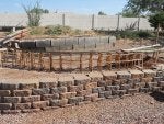
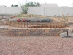
The project has gone from "When I win the lottery" size to "Darn that's a lot of bricks to carry."
200 bricks for around the tree and roses then 1600 (10+ pallets) for that 20" wall. Add 14 dump truck loads of dirt, trench in 2 power drops (1 20 amp the other 15 amp) and a water supply. That's were I'm at so far. As soon as I figure out how to add photos to this site I'll do so. I'm sure I'll get plenty of feedback, along with chuckles, guffaws, and shaking heads from members. Alll suggestions are appreciated, although some will be taken with a grain of salt, I'm sure.