G Scale Model Train Forum banner

Streamlined Garratt build log

53K views 94 replies 21 participants last post by  StackTalk  
#1 ·
I have been thinking about this project for a long time and finally decided to do it
These monsters ran in Algeria from 1932 till they were abandoned during WWII because the Allied troops could not maintain or run this sophisticated locomotive. They were all consequently scrapped.
The first edition had Walschaerts valving but they were converted to Cossart valves which allowed for earlier cutoffs. This was the ultimate downfall of the engine as the reverse mechanism was electrically controled and there was no mechanical backup in place for when the complex electrical system failed.

There are no measured drawings for it and only a few dimensions but enough for me to build a model.

Here is what I had to start with

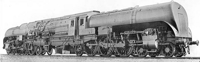
Photos of the engine left and right with a coal load in place
Image


Image


And with the three hatch covers over the coal bin
Image


Here are two drawings which are a little off vs the photos but seem to be very close to scale and show great detail.
Image


Image


Based on the dimensions I had and the photos and drawings I had, I drew up a 1/32 scale drawing of the model I will be making. It takes up four sheets of paper taped together and the pencil doesn't scan very well but you get the idea.
Image


The boiler is short and fat. The fire box will be 3" x 4" which will be good but the tubes will be only 5-3/4" long so I will be using 1/4 ID tubes.
Image


The prototype wheels were 71" drivers, 1 meter bogies and 1.1 meter pony. I ordered the cast iron wheels from Wallsal in England last week and was surprised to see them show up on Thursday
Image
]

I start by mounting the wheels in the chuck using the outside jaws and here I am turning the back to square it up and get to the back of the spokes.
Image


Before I remove the wheel, I drill and ream the axle hole. Now the back and axle will be true to each other.
Image


These are two mandrels I made up from steel bar stock the driver one is 5 mm and the small wheel one is 5/32"
Image


The wheels are then mounted in the mandrel and the tread is turned to true it up and remove the cast iron scale. With the tread trued up, the wheel is again placed in the chuck with the outside jaws and the hub is turned. Now the wheels are ready for the final tread profile which will be done on Dennis' lathe on Tues.
Image


Once the wheels are finished and I am sure of the flange diameter, I will complete the frame rail drawings. In the past I have done these on my mill but now that Dennis has his CNC mill going, we may try it out here.
 
#2 ·
We used Dennis' 12 x 36 lathe and his tread form tool to finish up the wheel machining
Here is a very simple crank pin drilling jig. I just drill and ream a hole in a piece of scrap material the size of the axle hole and mount it flush in the vice with a short piece of axle rod which has a centering hole to zero my measurement
Image


Then I drill out all 12 drivers so the radius is exactly the same for all. You can see the nice profile the wheel tread has now.
Image


I sketched out the side and drive bars to scale and Dennis converted my drawings to CAD and machined them on the CNC mill
Image


I bored and reamed the cylinders similar to the Uintah build but as the stroke is shorter, my wood wedge technique wasn't working. The sharper angle made them slip in the vice. So, I glued them in place with CA and just knocked them off and cleaned the vice jaws up with a scraper when I was done.
Image


The port is started with a 1/16" end mill and then it is used to open the area at the end of the bore. A 1/16" drill is then used to drill to the valve port. The short stroke and 5/8" bore make all of the hole drilling close so it had to be very accurate.
Image


I still have some machining to do but I have most of the cylinder components finished.
Image
 
#4 · (Edited)
Streamlined Garrats; searching for the illusive PRR T1 Streamlined Garratt can be a daunting task. But as you can see from this rare photo well worth the effort:
Image

Google Search Terms; "PRR T1 Garratt"
https://www.google.com/search?q=PRR+T1+as+a+Garratt&rlz=1C1CHFX_enUS578US578&oq=PRR+T1+as+a+Garratt&aqs=chrome..69i57&sourceid=chrome&es_sm=122&ie=UTF-8#q=PRR+T1+Garratt


However Ontheotherhand... for streamlined Garratts, here are some search terms for you to try and following is a sample of the links those search terms yielded.;
Google Search Terms Used:
"Streamline Garratt"
"Algerian BT class garratt locomotive"
"Algerian Garratts"

The last entry below is to the Yahoo Group: Garratts. If there is anywhere to ask for Garratt info those folks seem to know more than everything on Garratts.

Dieselpunks: Algerian Garratts;
Dieselpunk is an art style that blends the spirit of the 1920s - 1950s with contemporary technology and attitude.
http://www.dieselpunks.org/profiles/blogs/sunday-streamline-67-algerian-garratts

THE GARRATTS OF ALGERIA
http://myweb.tiscali.co.uk/peclegg/sncf/articles/article_2007_01.html

Forum: Board index » Railway Preservation News » Interchange
http://www.rypn.org/forums/viewtopic.php?f=1&t=23521&sid=1c09310fee0226cd7f53e26d7d1c9589

Garratt
(From Wikipedia, the free encyclopedia)
Garratts around the world
Algeria[edit]
In Algeria 29 4-6-2+2-6-4 Garratts, constructed between 1936 and 1941 by the Société Franco-Belge de Materiel de Chemins de Fer at Raismes in Northern France, operated until the Algerian independence war caused their withdrawal in 1951. This class, designated 231-132BT, was streamlined and featured Cossart motion gear, mechanical stokers and 1.8 m (5 ft 11 in) driving wheels, the largest of any Garrett class. On a test in France, one of these achieved a speed of 132 kilometres per hour (82 mph)—a record for any Garratt class (and indeed any articulated class).[11]

WorldRailFans.info → Main → The RAILWAY DISCUSSION FORUM
Topic: 231-132 BT Beyer-Garratt
http://www.worldrailfans.info/forum/index.php?/topic/1948-231-132-bt-beyer-garratt/

To help you find the builder: Garratt locomotives from other builders
http://www.beyergarrattlocos.co.uk/other.html

Google Search Algerian BT class garratt locomotive (Images)
https://www.google.com/search?q=Algerian+BT+class+garratt+locomotive&rlz=1C1CHFX_enUS578US578&es_sm=122&biw=1600&bih=744&tbm=isch&tbo=u&source=univ&sa=X&ei=QrPOVJ_DF8S-ggSImYPwBQ&ved=0CB0QsAQ

Yahoo Groups: Steam Locomotives Technologies:
[steam_tech] Re: Algerian Garratts
https://groups.yahoo.com/neo/groups/steam_tech/conversations/topics/4479

Yahoo Groups: Garratt Talk
https://groups.yahoo.com/neo/groups/Garratt/info


Good luck hunting. :cool:


PS; Posts like this are an example of the extreme measures one goes to for excitement during the Super Bowl pregame warmup(?) :eek: :confused:
 
#5 ·
Must have been a very interesting machining job to get 4.200 hole spacing in a part with .4555 overall length ... ;)

Thanks for the detailed step-by-step information. I'm really looking forward to following this project.
 
#16 ·
From what I've read, Baldwin Locomotive Works could not come to terms with Beyer Peacock to license the Garratt design in the USA. I don't know if American Locomotive even looked into a licensing agreement.
 
#8 ·
Totally fascinating project. Makes you wonder why anyone thought streamlining was important for a machine that rarely went more than 30mph

As you get into the design of the steam delivery system, I do have an Aster AD60 which you are welcome to inspect. I'd also be happy to lend you the AD60 build instructions. I live in Los Altos Hills just off i280 and work in Palo Alto which I think is close by.

Robert
 
#9 ·
Robert
Thanks for that offer. I have always been impressed with Aster locos and have never had the opportunity to inspect their Garratt
As for the streamlining, this Garratt reached speeds of over 80 MPH

Here is my current progress

I have finished the machining on the pistons, valves and cylinders. I am waiting to make the piston and valve rods till I have the expansion link and crosshead mounted.

I sketched out the frame design and Dennis converted it to CAD and printed a scale drawing of it.
I secured the four frame pieces together with three dowels and did the cutouts with the band saw and a 1/8" blade. The cylinder mount holes were drilled out on the DRO mill. In the past, I have done the cutouts for the axle boxes on my mill but now that Dennis has CNC on his very ridged mill, they will be more accurate than ever before so off to his house for the final machining.
Image


While I am waiting for the engine frames, I decided to get started on the boiler. The design will be similar to those I have made before which is locomotive style with a ceramic burner. I have found that the ceramic burner seems to heat better with a dry firebox as the majority of the radiant heat goes straight up and the larger element and crown sheet seem to work better than the smaller wet firebox. This boiler is short and fat. the tubes are only 6" long so I am using 1/4" ID tubes. Here I am checking the size and placement against the scale drawing. It looks like it will interfere with the pony wheels but that is because of the photo angle. They will just clear
Image
 
#10 ·
The boiler is now complete. I have taken a lot of photos to show the process

The first thing is to cut the tubes to length and then solder them to the throat sheet. The tubes are inserted into the end plate to keep them parallel and then the throat plate is put on. Clips which are made from music wire are placed on three tubes to keep the plate from sliding down as it expands from the heat.
Image


It is then soldered from the top and the job is checked to make sure the solder flowed to the back side
Image


The assembly is then set in the boiler shell and is held in place with 00-90 screws. As this is in the dry firebox area, brass screws are ok
Image


The front tube sheet is then set in place and is secured by cutting small pieces of 14 ga copper wire and tapering them with a file on the lathe to about .054 at the tip and then driving them in to a # 54 hole
Image


The backhead id drilled out. The four holes in the center are for the window cutout to the left is the front superheater hole and on the right are the two holes for the rear superheater which will make a U in the firebox. the three holes at the top are for the steam pipe.
Image


I added this arch to the throat sheet which will keep the steam pipe from dropping down below the dome
Image


14ga copper wire is threaded to 0-80 and these are screwed in to the throat plate and backhead to support the crown sheet during the solder job
Image


Crown sheet and backhead with supports in place
Image


The boiler is being setup for soldering. Note the curved piece of solder between the throat sheet and boiler shell
Image


Note the white out in the holes next to the crown sheet. this will keep the solder from flowing in to them.
Image


We used a large turbo propane burner to heat the entire mass and here is an acetylene/air torch getting in to the fire box. Note that the top right stay has a round snippet of 1/32" solder around it and you can see another above it which will melt when the torch hits it.
Image


Firebox came out with no leaks on the first firing
Image


And the finished boiler
Image

Image

Image
 
#11 ·
Hi Bill:
Thanks for posting the photos...interesting boiler work...at first I thought "WOW, why is he using a fully dry firebox?"...but then I went back and realized this was for a ceramic burner...seems to make perfect sense because as you say with a ceramic burner most of the heat is going straight up. Looks like with the fat boiler there is a lot of headspace for steam...that coupled with the large burner area should provide a for a large amount of steam...a good thing since you'll need a lot of steam to feed two sets of cylinders.
I'll be watching your build closely...I have at the back of my bench a long range project building a K1 Garratt...boiler for that loco is short like yours, but smaller area for the firebox...I've built the boiler as a coal fired version which of course could be fired by a ceramic burner, but with the small size I don't think I'd get enough heat...it will be interesting to follow your build to see how things work out.

Best Regards,
Cliff
 
#12 ·
Thanks Cliff
The ceramic burners are nice in that they burn steadily and are very quiet but they don't have near the heat output of coal.
From what I have read, a dry firebox for coal needs to be mechanically put together or the heat of the coal fire will melt the silver solder
I did a wet firebox on my Heisler and a dry one on the Uintah. Both fireboxes had about the same outside dimensions. It seems like the dry firebox with the larger crown sheet and ceramic plate steams the best. but they both work good.
And, as you can see from the photos above, the dry one is a lot easier to make.
 
#13 ·
Bill Allen wrote:
(snip)...And, as you can see from the photos above, the dry one is a lot easier to make. (snip)

Yes Bill, I certainly noticed the dry firebox seems easier to make...that's the key thing that intrigued me about the design....thanks for the additional info on boilers for your prior locomotives...I'll keep all this in mind for my next project!
 
#14 ·
Great workmanship, there. :)

I was wondering how you arrived at your tube size and placement? Did you follow any formulas?

Some of the fitting holes at the top look larger than I remember from the Unitah thread? I wondered if you had a reason?

Thanks,
Matthew
 
#15 ·
Matthew
I think the formula is from Martin Evans and I don't remember it exactly but it works out to about 1/20 of the tube length to the tube diameter. This is for coal but it seems to work for ceramic also.
As the Uintah is narrow gauge, there was plenty of height in the cab to pull the steam off the top of the boiler. In this 1/32 model, I need to come off the backhead with a tube going to a steam dome in the middle of the boiler, thus the larger hole (7/16" - 24)in the middle on top.
The filler and manifold holes in the back are the standard 3/8" -24
 
#17 ·
I was posting some stuff and was 3/4 of the way through and I hit the X by mistake and closed the program so now I will post a few and finish up at a later date.

Here is the steam tube for the throttle
Image


And the throttle mounted. the two outlets are one for each engine.
Image


Now back to the chassis. The axle blocks are cut and milled to shape and drilled for the axle holes and the spring holes.
Image


And set in place. Note the bronze bushing for the axle.
Image


The side rods are now placed over the axles to ensure there is proper spacing on all components.
Image


The rear axle is fitted with a ball bearing eccentric.
Image


The axle pump is fitted with a scotch yoke and bronze piston
Image


The pump is mounted. the shoulder bolt is the rear truck pivot
Image


The rear cross member and truck support is curved to clear the yoke.
Image


The rear truck is set in place and measured up
Image


The rear wheels need to be as close to the drivers as possible for the firebox clearance so I am holding things in place with the vice grips to check clearance in all positions.
Image
.

This is a poor man's rotary table for cutting the slot in the truck
Image
 
#18 ·
The front trucks are not as complicated as the rear pony truck. A stretcher is mounted in the frame between the cylinders with a 8-32 hole tapped out. The pilot truck rails are cut out of 1/8" x 1/2" brass bar on the band saw. The crossmebmer is from 1/8' X 1" brass flat bar. the shoulder bolt and washer are turned on the lathe. The spring is from cut-to-length stock from McMaster
Image


The prototype had a single bar crosshead but there isn't a lot of detail available so I just came up with a design that looked good to me. I take the 1/8" tool steel stock and polish it on the bench belt sander. It is so hard that the sander is all that is needed to polish it. Then in the four jaw chick on the lathe, I turn the ends down to 1/16" round which go into 1/16" holes drilled in the cylinder head and rear brace.
Image


Here is the underside of the mostly finished chassis. The other chassis does not have an axle pump.
Image


In this side view, you can see the rectangular bracket above the front drivers which supports the crosshead bar and will hold the expansion link for the yet to be made valve gear
Image


And another view
Image
 
#19 ·
Hey Bill...I noted with interest your steam tube...could you give a bit of explanation regarding this?...I see the tube coming up into the steam dome, and it looks like a solid rod exiting the backhead...is the steam valve itself inside the boiler below the steam dome, or is it perhaps located in the piece you have mounted on the backhead where the two outlets are located.

I'm in the middle of making the internal steam valves for our Lawley project and due the complexity I'm very interested to see the designs of others...looking for simpler solutions for future projects.

Best Regards,
Cliff
 
#20 ·
Hi Cliff
That is actually a 5/32 tube coming out the back. Here is a photo of the assembly. The valve body has a 5/32" by 1/8 deep hole where the copper tube is silver soldered to it which doesn't show here. In order to get the nice bend in the tube, i had to anneal it which makes it pretty soft. If you go up to the middle of the boiler photos, you will see where I added an arch to the throat sheet to keep the tube from drooping down over time. The tube is fished through the hole in the backhead and guided through with the end pointing sideways and then turned to vertical when it is lined up with the dome hole.
Image


The hole in the backhead is countersunk to retain the o-ring seal
Image


Here are the working parts of the throttle valve. Because of the four 5/8" cylinders and because I will be using RC, I have a very blunt needle valve as I will be limited in the throttle opening
Image


Here is a rough sketch of the valve
Image
 
#23 ·
Hello Bille 1906 and all:
I am wondering why those cylinders have their valve chest on top Bille 1906? The real loco was fitted with Cossart valves which are nearly impossible to make in gauge one, granted. Nevertheless that valve gear was fascinating to watch in action: The big excentric rod was off the crank like any walshaerts gear loco, but the comparisson stops here, it was weighed in order to counterbalance dynamically the piston and cross heads weight in order to reduce hammer blow. Then it was balanced with an outside rocker, whose principle is identical to the rockers on most nineteenth century US engines with inside excentrics and rockers to outside valves. Then there is the "bielle dentelle" (literally lace rod!) wich transformed the to and fro movement into a rotary one this rod had a spring system which could give a litlle, I suspect that there was also an adjustment device in it for fine tunning of the gear. This rotary movement was given to a sort of flywheel with a crank called : le "tourne broche" or litterally ( the rotisserie crank!) (French railroad slang was as flowery as US railroad slang as you can see). This rotary movement was comunicated in turn by gears to the central cam axle, paralel to the tourne broche axle sitting right in the midle of the steam chest. The cams lifted alternally four sets of valves through levers that went up and down in sequence of course. This action was true wonder to behold of course. So on my NORD De Caso tank 1-4-1 TC in SNCF parlance 4 -1200 in NORD parlance contemporary to the garrat, (but which remained in service untill 1970 in the Gare du Nord to Valmondois service (my home town) and to Persan Baumont , which is why I remember them very well) I shall use slip excentrics in board and a fake Cossart with all the exciting action outboard. Watching this show makes Walshaerts or Stephenson gears look like a bore. But whatever keep up the beautifull work. By this time next year we should have photos of two projects fitted with the Cossart Gear.
 
#24 ·
I think you answered your own question of why I didn't attempt to fabricate real Cossart valving. From what I have read, these were originally fitted with Walschaerts valving and later converted to Cossart so my plan has been to model the pre-Cossart loco.
However, after looking at the only photos available if the loco which all have Cossart, I am thinking I may customize the Walschaerts linkage to at least resemble some of the Cossart levers.
Stay tuned
 
#25 ·
I am moving around a little here. Usually I try to finish every component before moving to the next but I wanted to get a good feel for the size and balance of the loco

The center frame starts with a simple box frame which pivots between the two rear drivers on each truck. because the bunkers are above the pivot and the rear trucks and axle pump are below, it would require major disassembly of components to get to it, for separation of the center frame from the power trucks. I used a similar setup to what I did on my Heisler

The riser is effectively made into two pieces which are held together with a set screw.
Image


The bottom section is soldered to the truck crosmember. I finally broke down and bought a pound of 1/32 stay brite. It was expensive but should last for a long time. Here I ring it around the riser and just heat it up till it flows into the joint
Image


Here it is mounted. You can see how it would be impossible to get to a screw from the bottom with the axle pump in the way
Image


Here the two pieces are joined. the pivot point is just below the screw and is between the risor and the upper stretcher
Image


This shows how the truck is released with a twist of the Allen wrench
Image


And here is the center frame mounted
Image
 
#26 · (Edited)
Join Date: Feb 2011
Posts: 93


Image

Good to hear your intention Bille 1906, Alas the first séries of Algerian garrat in standard gauge have a totally different esthetic, I can't post photos on this forum to show you but here is the link to a good photo of one:

http://www.dieselpunks.org/profiles/sunday-streamline-67-algerian-garratts

In that site if you look at the third photo you have an idea of its esthetics, quite diferent from the streamline one. Do note though that there were two railway companys in Algeria the PLM algérien and the ETAT algerien. these merged around that time (I am not an algerian railroad expert) But the streamlined ones were not conversions of the older class ordered by the PLM algerien. They were a new order from the Franco Belge which incorporated features from the NORD railway of France. I read somewhere that the motive power department of the NORD was quite pissed off that the Franco Belge incorporated their valve gear without asking them...
I also have a photo of the Nord Mikado tank Roger Marsh did for my friend John Wood of the SNCF society, live steam in gauge one. which I can't post for the same reason...
But I am impressed at the speed you turn these wonders out keep up the good work.
Simon
 
#27 ·
I must make ammends, Bille:
I have just found a photo of the PLM algerien Garrat fitted with Cossart gear! To my utter surprise as in France these are always mentionned as two different series, although they are evidently an evolution from the early one to the latter. There isn't much info on these in France and I am more interested on French prototypes than Algerian ones, although that particular loco does have a very strong appeal to me because of it's NORD heritage. I just couldn't immagine PLM engeneers adopting a NORD practice piecemeal; the two are as opposed as Greek architechture and Gothic. Yet here it is, and as always there is a prototype for everything. So, inversly, it just might be that one of the older non Cossart equiped Garrats could have gotten the beauty treatment (IE: the streamlining)...
 
#28 ·
I finished up the rear chassis this week and tested it on air. It ran smoothly in both directions at 5 psi and I could easily count the wheel revolutions when I slowed it down. I will be adding cylinder covers and a replica of the Cossart valving. Dennis and I are working on a design which will have a rotating crank and valve stems which will go up and down

The return crank (eccentric crank) is critical to the valve operation and timing, The distance between holes needs to be within .001" to get the correct timing. Here Dennis is machining them out on the CNC
Image


And cleaned up with the clamp bolt in place.
Image


The automatic drain cocks are made as follows
The 3/32" rod on the left is drilled out to .040" and a shoulder is cut to fit into a 1/16" hole that will be drilled into the 3/16" piece of rod on the rt.
Image


The two are silver soldered together.
Image


Then chucked in the lathe, drilled and then finished up with a D bit
Image


A 1/8" SS ball is inserted and the cap which is turned slightly oversize is pressed in. This will be removable by grabbing and twisting with a pair of pliers. The valve it's self is also pressed into the cylinder and blue loctite is used to further secure it.
Image


Here are the Walschaerts components left to right: valve, valve stem, combination lever and link, radius rod, expansion link, link block, return link, return crank.
Image


the heart of the Walschaerts valving is the combination lever. Note how the valve stem is connected to one hole and the radius rod is connected to a hole below it and how the rod ends are rounded for clearence as the valve and combo lever move about. If you see a model with the stem and radius rod at the same level, it is not Walschaerts and will perform poorly.
Image


Here is the expansion link with the block in somewhat mid gear. Reverse is up and forward is down. On the Garratt, one is up and the other down. The reverse lever and link are shown lifting the block.
Image


So, here is the whole setup. You can seethe drain cocks in place. They will be partially covered by the cylinder cover.
Image


And the whole thing as it is so far. The front chassis is not complete but I made all of the parts fo it as I went along on the rear one.
Image