G Scale Model Train Forum banner
1 - 20 of 26 Posts

peninsok

· Premium Member
Joined
·
55 Posts
Discussion starter · #1 ·
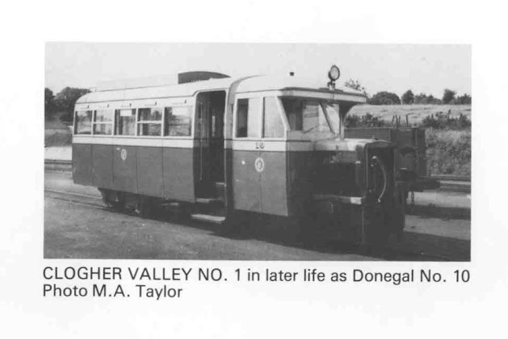
Last year I attended the opening of the Kapiti Model Engineers (West Coast, North Island, New Zealand) new clubrooms. On display was a 5"gauge model of an Irish Railcar which really appealed to me. A search on the internet and G Scale Mad enabled me to obtain photos and line drawings of the Clogher Valley Railcar #1.

Image

Image


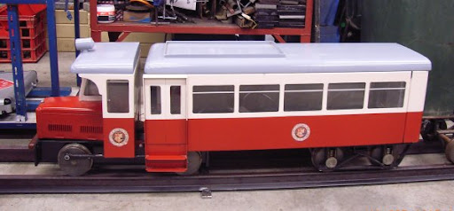
The 5" gauge model that caught my attention

I intended building one in 1:24 scale

The drawings were enlarged to 1:24 scale and a start made.

Image


Here the cab back and side drawing is glued to 1mm thick brass sheet ready to be cut out

Image


Here a start has been on the cutting out using a jewellers saw with 52tpi blade


Image


Image


Image


Not having access to a cad program, the drawing were prepared using MS Publisher


Image


Part way through the soldering process


Image


Soldering nearly completed and clean up started

Image


Image


The Railcar will be powered by a USA trains motor block.


Image


The axle extensions will be removed and the wheels will be drilled and tapped for the crank pins as the railcar was rod drive from an internal combustion engine. The rods will be made from either brass or steel. haven't decided which yet.


The next part of the process will be the chassis and it's mounting on the motor block. Following that will be the cutting out and forming of the passenger compartment. More photos will follow if there is any interest
 
Discussion starter · #5 ·
You are well under way.
Mine has stalled a bit at the moment as I have been involved with a Pipe Band Contest and have just about completed the financials for that, so will be able to progress further.
I will be in Ranchester, Wyoming,in July, following the Garden Railway Convention in Denver.
 
Discussion starter · #7 ·
Having drawn up the sides and rear of the passenger section, this was attached to the 1mm brass sheet with spray adhesive and a start made on cutting out.

Image


Two hours later the windows and door openings have been cut out ready for final filing

Image

The cutting out was done with a fretsaw, (hand scroll saw) fitted with a 52tpi jewellers saw blade. As the throat of the fretsaw was only 250mm (10") I had to modify the frame by bending the end of the throat out about 75mm (3") to allow access to the rear windows. Funnily enough, the modification to the fretsaw has made it easier to use, so it will stay modified.


More later
 
Discussion starter · #8 ·
Another 3 hour session and the passenger compartment is taking shape

Image


Passenger compartment and cab lined up for checking

Image


Photos taken with wide angle lens, hence distortion
 
This is looking really nice! Watch for a cover story on a really nice Irish prototype layout in Garden Railways. The builder, Neil Ramsay, has made a couple of these railcars, too.
 
Discussion starter · #11 ·
Further progress has been made with the fitting of the entry doors to the passenger compartment along with strengthening angle at floor and roof positions. The 'tumblehome' on the lowersection of the sides has also been formed.

Image


A start has been made on the bogie (truck) to go under the the passenger compartment


Image


The drawing for the two bogie side glued to 1.6mm brass ready for cutting out.


Image


The two bogie sideframes cut out ready to have the axle holes drilled. They were cut using a piercing saw with 52tpi blade. The axle boxes will be soldered in position once the bogie stretcher has been formed.
 
Discussion starter · #13 ·
The component parts for the bogie (truck) for the passenger compartment are completed ready for assembly

Image


The assembled bogie fitted with Bachmann 25.4mm wheel sets

Image


And in position under the passenger compartment.

Image


The bolster has been machined and will be mounted to the passenger compartment floor. Yes, it does sit that far forward.


Ian
 
Discussion starter · #15 ·
Hi

As I mentioned earlier, I had intended using a USA Trains motor block as a power unit. I am now thinking of making up my own unit. What have you used for your motor and gearbox?


Regards
Ian
 
Discussion starter · #16 ·
Posted By Rastun on 04/05/2009 11:30 PM
Very Nice. I've been working on one of those myself but life has gotten in the way for quite awhile. Mine looks like this right now.

Image


As mentioned earlier I had intended using a USA Trains motor block as my power unit. I am now thinking of making my own power unit. What motor and gearbox have you used?

Regards
Ian
 
Discussion starter · #19 ·
Work on the rail car progressed a little further today with the frames for the power unit cut from 1.5mm brass. One piece was marked out with centres for the axles and lay-shaft as well as the screw holes for the the frame spacers. The screw holes were drilled in the marked out piece and a second piece of brass was clamped in place and the 1.5mm screw holes transferred through. The second piece was then Tapped for 2mm screws and the two pieces fastened together. This allowed both to be cut out at the same time. Cutting was again done with a fret saw fitted with a 52tpi blade.

Image


I will be using a HLW motor/gearbox which will drive one axle via Serv-O-Link Delrin sprockets and chain. Bachmann 25.4mm wheels will be used and will be modified to allow for the fitting of the connecting rods between the two sets of wheels.


Image


Frame spacers will be made from 6.4mm brass bar and attached with 2mm countersunk screws. Bushes will be fitted for the axles and lays-haft to run in. Electrical pick-up will be by LGB plungers bearing on the back of the wheels.
 
1 - 20 of 26 Posts