Since some of you fellows have shown such an interest in old farm tractors for your layouts. I dug up some pix and catalog cuts of a visually interesting, yet relatively simple one. It's of about WWI vintage (built from 1910-27), so it will work on most layouts, either new, in use, derelict in a hedgerow, or on a flatcar headed for the scrapyard.
I bring you the Flour City tractor, made by the Kinnard & Sons Mfg. Co. of Minneapolis, Minn.
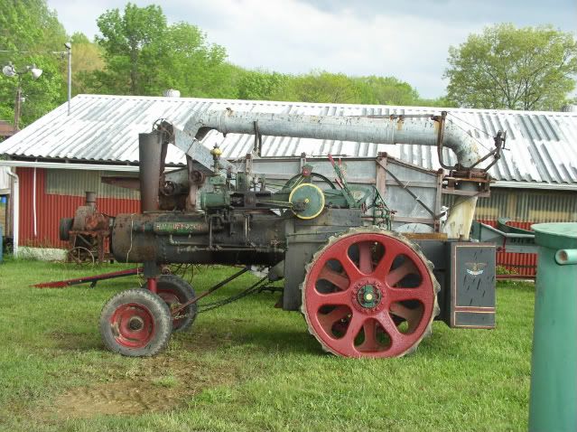
Flour City tractors were made in 5 models in 4 sizes: I've included some dims from the catalog to help you scale the rest.....
The 12-24 Junior-
![Image]()
![Image]()
![Image]()
Belt Pullley..................26 x 71/2 in
Front Wheels.............................. 38 x 5 in.
Traction Wheels...........60 in., Face (R-12 in., L-14 in.)
Length.........................................152 in.
Width..........................................84 in.
Wheel Base..................................92 in.
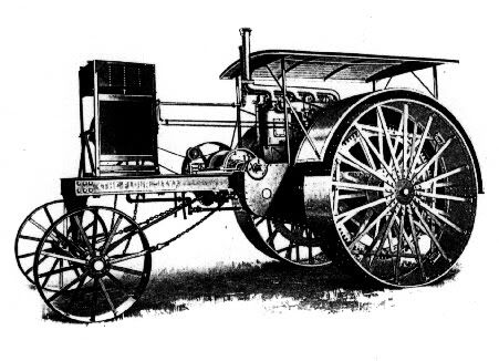
The 20-35 -
![Image]()
Belt Pulley .............................................................................. 26 x 8
*Traction Wheels .................................................................... 6 ft. x 18 in.
Front Wheels .......................................................................... 42 x 8
Wheel Base ............................................................................ 9 ft.
Width Outside Trac. Wheels ................................................... 80 in.
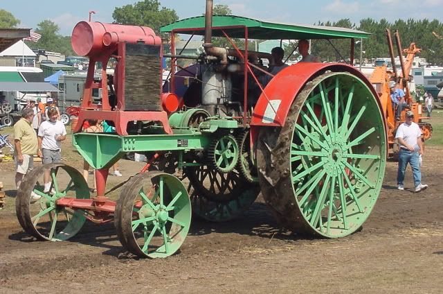
The 30-50 -
![Image]()
Belt Pulley .............................................................................. 32 x 9
*Traction Wheels ................................................................... 7 f t. x 24 in
Front Wheels ......................................................................... 48 x 9
Wheel Base ............................................................................ 11 ft.
Width Outside Trac. Wheels ................................................... 96 in.
The 40-70 -
![Image]()
![Image]()
Belt Pulley ............................................................................... 34 x 10
*Traction Wheels .................................................................... 8 ft. x 24 in.
Front Wheels .......................................................................... 48 x 10
Wheel Base ............................................................................ 13 ft. 6 in.
Width Outside Trac. Wheels ................................................... 111 in.
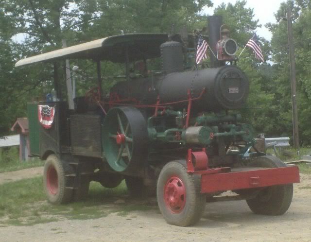
And the 40-70 special road tractor -
![Image]()
![Image]()
![Image]()
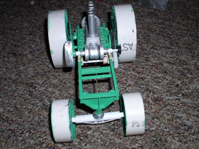
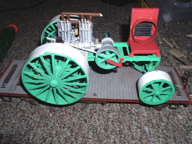
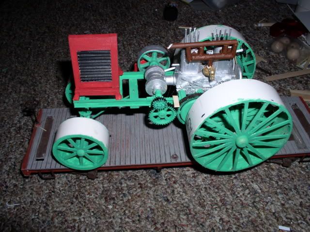
Okay, so now you're all saying 'simple?' It should be if you break it into steps. To help with that, here are some original 1919 catalog cuts to get us started:
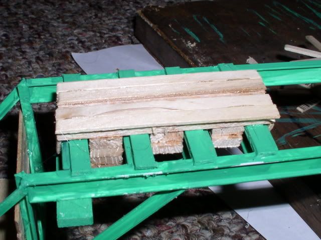
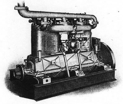
engine bed with crank -
![Image]()
engine cylinders and heads -
![Image]()
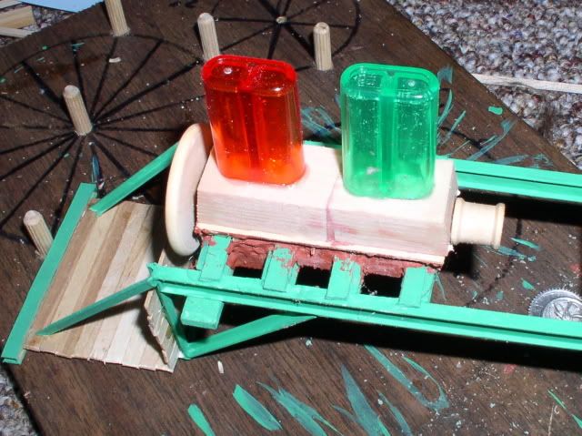
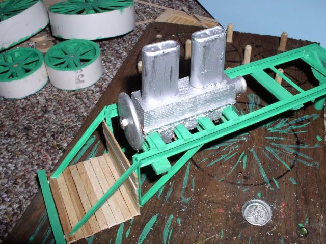
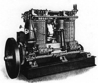
Engine assembly -
![Image]()
![Image]()
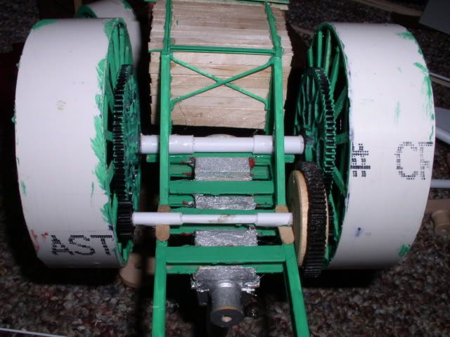
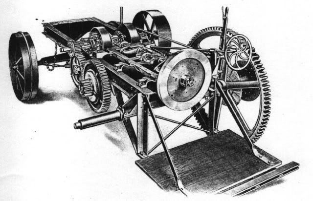
Gearbox and frame layout -
![Image]()
![Image]()
Rear wheel with bull gear -
![Image]()
Operator's platform -
![Image]()
And some pix to show scale -
12-24 plowing
![Image]()
30-50 threshing
![Image]()
40-70 threshing
![Image]()
40-70 with steam traction plow
![Image]()
40-70 special with grader
![Image]()
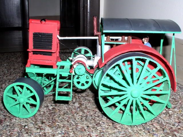
anybody up to the challenge? I have some ideas on how to build it. But feel free to share yours....
I bring you the Flour City tractor, made by the Kinnard & Sons Mfg. Co. of Minneapolis, Minn.
Flour City tractors were made in 5 models in 4 sizes: I've included some dims from the catalog to help you scale the rest.....
The 12-24 Junior-


Belt Pullley..................26 x 71/2 in
Front Wheels.............................. 38 x 5 in.
Traction Wheels...........60 in., Face (R-12 in., L-14 in.)
Length.........................................152 in.
Width..........................................84 in.
Wheel Base..................................92 in.
The 20-35 -

Belt Pulley .............................................................................. 26 x 8
*Traction Wheels .................................................................... 6 ft. x 18 in.
Front Wheels .......................................................................... 42 x 8
Wheel Base ............................................................................ 9 ft.
Width Outside Trac. Wheels ................................................... 80 in.
The 30-50 -

Belt Pulley .............................................................................. 32 x 9
*Traction Wheels ................................................................... 7 f t. x 24 in
Front Wheels ......................................................................... 48 x 9
Wheel Base ............................................................................ 11 ft.
Width Outside Trac. Wheels ................................................... 96 in.
The 40-70 -


Belt Pulley ............................................................................... 34 x 10
*Traction Wheels .................................................................... 8 ft. x 24 in.
Front Wheels .......................................................................... 48 x 10
Wheel Base ............................................................................ 13 ft. 6 in.
Width Outside Trac. Wheels ................................................... 111 in.
And the 40-70 special road tractor -

Okay, so now you're all saying 'simple?' It should be if you break it into steps. To help with that, here are some original 1919 catalog cuts to get us started:
engine bed with crank -

engine cylinders and heads -

Engine assembly -
Gearbox and frame layout -

Rear wheel with bull gear -

Operator's platform -

And some pix to show scale -
12-24 plowing

30-50 threshing

40-70 threshing

40-70 with steam traction plow

40-70 special with grader

anybody up to the challenge? I have some ideas on how to build it. But feel free to share yours....