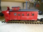
As you can see it is still a work in progress. The body parts are crude and only close to how it would look like on the RR.
So far the rotary assembly is complete, or so I think. Vacume cleaner vane, nothing new there, but I added pre vanes that will help push the snow into the vanes when spun in either direction. I added a directional flap to the top of the rotary assembly so the snow can be thrown to either side of the track.
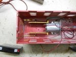
The rotary shaft is supported by ball bearings to reduce friction there. The rotary assembly will be driven by battery and an electric motor since I will be using it to clear a Steam Track, I can also use it to clear my electrified track.
I am presently on hold waiting for a delivery of very nice machined Stainless Steel U joints and still researching motors.
I want to thank Jerry from Neb and Sean from Mass for their suggestions and encourgement in this project. Enjoy, i have and still am.
So far the rotary assembly is complete, or so I think. Vacume cleaner vane, nothing new there, but I added pre vanes that will help push the snow into the vanes when spun in either direction. I added a directional flap to the top of the rotary assembly so the snow can be thrown to either side of the track.
The rotary shaft is supported by ball bearings to reduce friction there. The rotary assembly will be driven by battery and an electric motor since I will be using it to clear a Steam Track, I can also use it to clear my electrified track.
I am presently on hold waiting for a delivery of very nice machined Stainless Steel U joints and still researching motors.
I want to thank Jerry from Neb and Sean from Mass for their suggestions and encourgement in this project. Enjoy, i have and still am.