G Scale Model Train Forum banner

SP AM-2 Cab Forward Build

11K views 93 replies 18 participants last post by  ferroequinologist  
#1 ·
The AM-2 (Articulated Mogul) Cab Forwards were used for both freight and passenger service beginning in 1927 as compound engines and were eventually converted ti simple in 1929 and renumbered to the 3900 series
My build is number 3900
Image


I get my wheel castings from Walsall in GB but their web site has been blocked in the US from what they said is a virus threat. I was able to contact then via email and ordered 12 castings which came last week
Image


The castings have a ridge which is very true and is where I start my turning process
Image


The back is then turned till the spokes are exposed
Image


The axle hole is center spotted, drilled out to 3/16" and then reamed to 5 mm
Image


It is then mounted in an arbor and the front rim is turned to a 6 mm thickness
Image


And the diameter is rough turned to shape. The final tread will be done with the plunge tool on Dennis' large lathe

The wheel is then mounted in the external chuck jaws and the center hub is turned to .280" thickness
Image


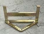
THIS IS A JIG I made for drilling the crank pin hole. I center spot it, drill to 3/32" and then tap to 4-40
Image


The center drill is adjusted to meet the drilled hole in the jig and the DRO is centered. It is then mover to .3375" which is the radius of the crank pin
Image


More to come
 
#58 ·
Thanks Gentelmen: I better understand now this important part of the Walshaerts. I think I had mixed up ideas about Walshaerts versus Stepehnson. It seems that the function was the inverse of what I thought. It comes from my being more historically minded than technically minded.
Anyways here is another example of this modified combination lever on the NORD railway of France Du Bousquet 4-6-0 or 230 D as the SNCF called it being restored in the AJECTA at Longueville today:

Image


This si the beast:

Image

One of gaston Du Bousquet's finest with his first 1911 Hudson.
 
#59 ·
Here is a photo of the bottom of the boiler. the superheater tube goes through the firebox and then through the tube to the smokebox where the steam line will be attached. The two front mounts are shown also
Image


Dennis made the smokebox door on the CNC mill. The piece on the left will be shaped on my lathe and 00-90 hex head screws will go in the holes
Image


finished and painted
Image


The cab end of the boiler
Image


The wrap for the wagon-top boiler is made in three pieces. The front is a straight piece wrapped over a sheet of Fiberfrax. The center piece is tapered and set over tapered hardwood strips. a sheet of card stock is fitted and then used as a template. The rear section is tricky as it flattens out over the firebox and needs to be trimmed to fit the slope of the cab
Image


the cab parts are cut out and then the front windows are cut on the mill with a 1/8" end mill
Image


The door openings are done with a 1/16" endmill. you can see the DRO in the background
Image


Rivets are embossed on the mill using a parallel as a guide
Image


Getting close to the 10 photo limit so I will sign off for now
 
#60 ·
i was asked about the rivet embosser I use and forgot to show it last time. These are both hand made. There was a company making these but the are out of business now. The punch on the left is just turned on the mill. The female part on the right has pairs of holes which are used for spacing. the rivet is punched and then moved to the next hole and the next one is punched. The hole is about 1/32" larger than the punch but varies depending on the material thickness
Image


Sorry but I didn't take any photos of the cab construction. Here is a shot of the soldering operation. What looks like a round bar is actually a square stick which is rounded over on one corner. It keeps the pieces square while soldering. Music wire clips hold things together. This is soldering the two front (top in the photo) corners. What the photo doesn't show is that the rear corners are being held in place with masking tape. They are far enough away from the heat to be affected by it. Staybrite solder is used.
Image

Here is the cab shell with a markup roof of card stock.
Image

More to come
 
#61 ·
I have to drill some precision holes in the front of the cab. I didn't do it before the solder job as I wanted to get the perspective where the attachments go. the holes are for the number board and classification lights.
I clamp a hardwood block in the mill vice so that it protrudes into the cab face and then clamp the face to the block with a large welding clamp. I put a brass strip under the clamp to prevent marring the face. The centering bit is in the chuck and you can see the three hole centers below. The block is black.
Image


Here is another view
Image


The number boards will be lighted. Here is part of them mounted
Image


The 3D printed number board parts
Image


Experimenting with light placement. the actual looks better than the photo but the LED is too bright so a resistor will be used
Image


the headlight
Image


And marker lights
Image
 
#62 ·
completed cab with number boards
Image


the engine has two distinctive dry pipes with complex couplers I start things on the mill
Image


Here are the pieces I will use for the mount. The flange is done on the lathe and mill. the short length of bar is for locating things during the silver solder process. the elbows were from McMaster and the flanges were cut off for sizing
Image


As these are for looks only, I used solid brass bar as it bends without kinking after annealing
Image


And mounted
Image
 
#64 ·
I have been working on small boiler parts this week. As they say "the devil is in the details"
I use an in-line lubricator valve that needs to be set only once so I use a screwdriver slot rather than a knob. I wand it to be inconspicuous and small. Here is the needle valve
Image


And the whole valve
Image


There are pipes/tubing on both sides that are mounted horizontally. I need mounting brackets for this. I start by milling slots 1/16" wide with a 1/16" spacing on a 1/16" thick sheet.
Image


On the table saw, I cut the mounting strips to .150 wide
Image


Image


Then the 1/16" brass rod is bent to shape and set in the slots with CA glue
Image

and painted
Image


Dennis cut the steps on the CNC mill and I silver soldered the mounting bracket on. I still need to figure out what the hand rail setup will be
Image
..

there are three steps on each side of the boiler. I mill the profile on a brass strip and cut to length. So far all of the permeant boiler parts are just primed
Image


The reverse cylinder is turned out along with the shaft and crosshead
Image


I have exceeded the number of photos so it is time to sign off.
 
#65 ·
U have been progressing on the build over the last couple of weeks. I have a lot of photos to show and only can post 10 so I will try to show the most informative of them.
Here is one of the air compressors. There is one on each side.
Image


and the 3D printed feedwater heater
Image


An exhaust T is used for the two chassis
Image


It will be inconvenient to adjust the throttle as on the Cab-Forward, there is no opening for the throttle shaft to protrude. I have room below the cab to put the throttle lever so I use a chain and sprocket setup for this,
Image

Here is what it looks like under the cab
Image


Here is the inside of the cab completed The knobs are for steam to the generator and tender water heater. The clack valve is below them
Image


Here is it with thr cab on. The 2032 battery holder has a built in switch where the red dot is.
Image

The pilot assembly took a lot of photos so I will post them next time.
Here is in interesting technique of using a carbide tipped router bit in the mill.
Image
 
#66 ·
The cow catcher has to be hand made as there are no castings available that will fit here. I start with a triangular base of 1/8
" brass strips cut to .200" the back strip has holes with .125" spacing and the front two have .169" spacing.
Here I am drilling the front pieces which will be cut at an angle afterwards.
Image


The bottom piece is then silver soldered together
Image


Now the back piece and rails are added
Image


I am using 3/32 copper tubing because it is soft enough to form without annealing, I support the front bars by inserting 1/16" music wire into the tubing of the front four bars.
Her is my setup. I have a 1/32" piece of sheet brass super glued to the mill vice where I will flatten the ends of the tubing. This makes each piece the same. Also clamped to the vice is a piece of hardwood with a notch which will center the piece for drilling
Image


Image


I can't get the miniature rivets I used to use but these doll house nails are close enough. I solder them in from the rear with Staybrite and cut them off and sand the rear down afterwards. The step is silver soldered together and the soft soldered to the pilot
Image


Image
 

Attachments

#70 ·
How it could look better in person than those photos is simply hard to imagine, as it looks absolutely stunning in the photos!

You Sir, make the difficult seem easy and the impossible seem somehow almost possible. That cow catcher alone would be a life's work masterpiece for someone like myself!!!
 
#76 ·
The tender is different from any I have done before. It is a semicylindrical or also known as whaleback. The early Cab-forwards had these as when they first started to run in reverse, they had the tender in front and the rectangular tender blocked too much of the view. when they converted to Cab-Forward design. they kept the Whalebacks for a while.
This presents a problem for me as this allows only a small opening under the walking deck and I need to store the fuel tank and hand pump there. My solution is to have a watertight tank inside the tender shell and have the shell attached to the floor with screws.

I start by drawing the tender in CAD and then parenting the end piece to scale. This will be used to check the bending shape of the shell as it has straight sides. I print out two ends, glue them to a 1/32" sheet and cut them out on the band saw and then sand to final shape.
Image


The end now is measures to get the width of the 1/32" brass sheet that will be the shell. Now I need to cut the small access hole in the middle of the sheet. I could use a saber saw but that would give me a rough cutout. An end mill would be the best but how could I hold the sheet in the mill. I decided to try this. I took two short lengths of brass strip and super glued them just outside the opening. I then inverted the sheet and secured the sheet in the mill vice clamping the strips on the ends not the sides which would break them loose.
Image


I then milled the opening out
Image


I then emboss the rivets
Image


Then over to David's to bend it on the roller and back home the ends are soldered on.
Image
 

Attachments

#77 ·
The tender now needs a floor and a walking deck.
the deck looks like it is made from four planks. I get that look on the mill using a v bit and then cut out the access hole for the fuel tank and hand pump
Image


The floor is a 1/16" sheet with 1/16" sides and a 7/16" square buffer at the ends. Here is the bottom view prior to soldering
Image


The crossmember that supports the trucks is 1-1/4" brass strip. I am using a piece of 1" brass square stock to hold the member in place while it is clamped in the vice. I can now drill holes to accurately match the holes in the frame,
Image


The deck is supported by 24 wedges which were made by milling a strip with a 45 degree router bit and then cutting off the wedges on the table saw. They were then attached with JB Weld
Image


Now the wedges are angled and the tender is round, so to get a good fit, I slide the deck over and back over a sheet of #80 sandpaper
Image
 
#78 ·
The walking board and some steps are added to the sides and ladders to the front and rear


Image


there is a strange setup on the side between the oil and water chambers. A solid bar member below the walking board and a wider strap above it. You can see the extra rivet rows in the pressurized oil chamber.
Image


The CNC milled truck side frame is attached the the inner frame with 2-56 screws. It is made to swivel by attaching one side with a stainless screw and the other side with a collar bolt
. Here I am drilling and tapping the frame.
Image


And the bolts


Image


Here one wheel goes over the allen wrench and the other three stay on the table

Image


And the finished truck
Image

there are five pipes going to the oil tank. I am guessing that there is an air line to pressurize the tank, a steam line to heat the oil, a supply line and I am not sure what the other two are. They are secured with these brackets which are staggered on the front of the tender

Image


Image
 
#80 ·
The corner steps, re-railer and center tool box hinges are 3D printed by Dennis. The masking tape at the top is to mark the holes for the hand rails
Image


The hatch covers are also 3D printed
Image
 

Attachments

#81 ·
The hand rails are bent to shape and the support legs are soldered on. They are then set in place and a drop of CA is applied at each attachment hole to set them. The next day the part of the rails that protruded into the shell is covered in JB Weld to permanently secure them.
Image


The shell is then painted
IN THE MIDDLE OF THE POST, I GOT A COOKIES REQUIRED SIGN BUT NO PLACE TO ACCEPT THEM SO I GUESS I AM FINISHED WITH THIS SITE