G Scale Model Train Forum banner
21 - 40 of 94 Posts
Wow Bille this is beautiful work. I like how you milled the bracket. I wish I could do that kind of work. But not doing vectorial drawing is a big handicap, for me. I alrady have a hard time learning how to use the lathe properly... Thanks for showing us how you do these very important operations.
Best,
 
Discussion starter · #24 ·
thanks Greg
Here is a look at the chassis with the valve gear in forward which is reverse in the Cab Forward
Image


The pilot truck is made with some small CNC parts done by Dennis
Image


The slot is on a radius from the closest axle
Image


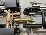
This is a dog bone connector used for the superheated steam lines between chassis
Image


The steam from the boiler goes into the top pipe and the dog bone fitting feeds the articulated chassis. the fitting on the left is for the lubricator. The pipe below is exhaust which can use flexible tubing because it is low temp and pressure
Image


The two chassis are tied together with this strap which has rubber bushings cut from tubing. These allow for some movement which is required as the two chassis are also connected to the boiler which expands and contracts at a different rate, The only reason for the straps is to keep everything together when the engine is picked up
Image


Here is the connection between the two chassis
Image
.

I then slit some silicone tubing and cover the copper tubing to insulate them
Image


The two chassis are then air tested
 

Attachments

Discussion starter · #26 ·
The rear deck railing is quite intricate. I need to make it in two parts as the hand rails have too many bends to be done in one piece. I start with the bottom first The rails are taped to the top to set the correct angle while soldering
Image


One side at a time does it
Image


finished and painted
Image


My usual axle pump with a ball bearing eccentric and scotch yoke make for a nice setup in close quarters
Image


I started on the boiler this week. The cuts to length are done on the band saw by rotating the pipe while cutting to get an even cut
Image


The 12" disk sander is set up using a framing square
Image

The pipe is finished off with the sander to get a perfectly square end.
Image


The cut for the firebox is made on the table saw. A 4x4 is clamped to the end to keep it from rotating during the cut


Image


The sides are annealed and formed around a wood cutout
Image

I have reached the 10 photo limit so will sign off
 

Attachments

Discussion starter · #27 ·
Here is the boiler shell with the smokebox piece. It is 22" long
Image


The firebox tube sheet holes are drilled out with a step drill. The small ones are 1/2" and the large superheater hole is 5/8"
Image


The front is set up with a piece of scrap brass to keep things level while soldering. The front tub sheet is slipped over the tubes to keep them aligned. The firebox tube sheet is silver soldered in place
Image


The joints are checked for pin holes
Image
 
Bill,

Wonderful work! I love the early cab forwards.
One note: the eccentric on the cab forwards was flipped so that the radius rod was still down when running in forward. This was a safety precaution so that if a pin breaks while running and the radius rod drops, the engine doesn’t suddenly change direction and cause more damage. In the prototype photo you shared you can see that the eccentric is following behind the crank pin while traveling in the CF’s forward direction.

Looking forward to more progress.
Anthony
 
Discussion starter · #29 ·
Thanks Anthony
We discussed this issue and it seems that the later cab forwards do run with the eccentric link down in forward but judging from the photos this early engine, the chassis was just turned around. The position of the return cranks and the combination lever indicates that the link is in the down position when it is moving toward the smokebox (reverse)
 
Discussion starter · #30 ·
One note is that the engine is parked in the photo so we don't know if it was in forward or reverse but the combo lever would have to have been reversed along with the return cranks. Gets confusing
 
Looking through my cab forward books - I can’t find a single photo of an early cab forward (MM, AM, or AC-1/2/3) where the valve gear is configured to run with the radius rod up when the locomotive is moving forward.

Since your model is outside admission rather than the prototype’s inside admission, the crank will have to be flipped from prototype photos to result in the radius rod being down in forward.

So I suppose it comes down to which you’d rather have match the prototype when watching it go down the tracks, the crank position or the radius rod position.

Anthony
 
Discussion starter · #32 ·
Like I said, it gets confusing. My model is outside admission but it has a cross plate which mirrors the inside admission valve gear. If you look at the combination lever, it is configured as the inside admission engines which have the expansion link in the lower position when going forward toward the smokebox. You can't flip the return crank without changing the combo lever or they will work against each other. In the 3900 photo, I believe the radius rod is above the valve stem but it also looks like the return cranks were flipped. Checking the detailed drawing the combo lever is as I mentioned. This doesn't make sense as it would run like this but be low on power.
It might be worth while to change the combo lever. I will check to see if it can be done without changing anything major.
Thanks for your input
 
I didn't notice the cross plate makes it so the combination lever can be arranged as inside admission. That's very clever!

The return crank, eccentric rod, and link are a functionally separate unit from the radius rod, combination lever, and union link. Their imparted motion is independent of one another, and their combined motion gives the valve its appropriate travel and timing. There's no reason the crank can't be flipped on your model. All this does is move the link's oscillation relative to the main crank pin from one side of the stroke to the other, reversing the engines travel. The only thing this should change is that the radius rod would then be down for "cab forward" forward.
 
Discussion starter · #36 ·
The tube sheet, rear sheet and crown sheet are soldered in place. The rear sheet is .093" material which makes for easy securing with three 0-80 stainless screws. The six stay rods are hammered to a flat on the ends to keep them from falling through.
Image


I make the stays about 1/2" long and after soldering, I cut off the excess on the band saw and then grind them on the bench grinder. The two small bushings are for banjo connections for the sight glass, pressure gauge, steam generator and tender water heater. the three small holes on the rear sheet are for the throttle and pickup tube which goes to the dome. the threaded fitting id for the clack valve.
Image


The front tube sheet is the last to be soldered. I do this because the small tubes and the boiler shell expand at different rates and if they are locked in prior to the firebox soldering, the high temperature could cause leaks at the tube sheet.
The small stainless bushing in the center covers the hole I made to turn the sheet on an arbor and now is threaded to accept the smokebox attaching screw.
Image


The boiler is cleaned up in citric acid between soldering jobs. This is just a box with a garbage bag liner
Image


I was lucky this time as I had no leaks after the first check
Image


The smokebox is copper with a river embossed brass sheet. the stack is fitted with a smoke deflector. There are no good photos of this so I copied the HO model I have. I originally thought it was gust a wedge but it is four small pieces silver soldered together.
Image


Image


The smokebox front has rivets with a 1/16" head and .038" shaft set around the edges. The smokebox door is being CNC milled by Dennis
Image
 
Discussion starter · #37 ·
The combination lever is sometimes hard to explain without drawing the figures but when the return crank is moving the valve stem in one direction, the combination lever advances the timing in the same direction. If you change the crank position without changing the combination lever, they will work against each other and retard the timing
 
Bill,

I understand what you're saying, but this is not affected by changing the location of the crank since the two are still rotating in the same direction.

The combination lever imparts enough motion to overcome the lap of the valve, and additionally lead (if any). This is a fixed motion imparted from the crosshead, and unaffected by the motion imparted by the link. The link then only adds additional motion to adjust the % of addmission/cutoff. Rotating the crank simply moves admission to the other side of the piston. The impact really is no different than moving the Johnson bar from forward to reverse.

If the combination lever was affected as you mention, then you would also not be able to change the locomotive's direction.

I'm racking my brain trying to think of how the crossplate might make a difference to this, but I'm coming up short. If it runs as is, moving the crank should not be an issue.
 
Discussion starter · #40 ·
Anthony
I have built about 20 Walschaerts engines and a few Baker gear which have combination levers. Early on I mistakenly had the return cranks flipped on a chassis and the engine barely ran. A little later, a friend was having trouble with a chassis not running and I found that the return crank and combination lever were not set up properly. It makes a big difference on my engine, the combination lever compensates for .040 lap so if it is going in the wrong direction it is like having .080 of lap.
Docstader is a great program where you can try your suggestion and see what happens

 
21 - 40 of 94 Posts