G Scale Model Train Forum banner
61 - 80 of 139 Posts
The opto circuit solves different issues.

Todd: a diode is cheap insurance, why not, right? What, 10 cents?

The Sierra can draw a lot of current, and can have reliability issues at higher voltages.

I spent some time getting good data on this, from several people who did professional installs for years. perhaps this page will help some: (read under the NOTES section)


Greg
 
Discussion starter · #65 ·
I recognize that. The difference would be in that if the power source were straight dc, you wouldn't need the bridge rectifier because you would alway be taking off of the + and - from the battery and these don't change like the wheel current can/does.

Also, DCC would probably need bigger caps (C3) to smooth out the incoming voltage to straight dc for use by the board. The bridge rectifer, C2, and C3 become unnecessary with batterys or a dc charge that does not change polarity.

Greg, you can correct me on any of this if I'm wrong.
 
Discussion starter · #66 ·
I've read your notes before. When you discuss max voltage, you don't note whether this is on terminals 7 & 8 or 2 & 4. An oversight?

BTW, the Sierra in my 44-tonner is still in the process of releasing its magic smoke. The piece that is smoking is just to the left of the LM chip and in your picture is the rectangle closest to and between pins 4 and 5. Looks like it was a voltage regulator.

Sierra offer repairs. I wonder if they could fix this.
 
max voltage on the normal battery terminals 4 and 2, but a good question to be specific, I believe the track pickup inputs are ok at or below the battery voltage.

I'll get the final word. The overvoltage one is interesting, those data came from SoundTraxx after a number of years asking what the real limits were.

Which picture is the one you refer to with the smoking component? The actual picture of the board?

They do not repair Sierra boards any more I am told.

Greg
 
Discussion starter · #69 ·
It is the component just above the left edge of the left switch, and above and to the right of what looks to be the bridge. You see what looks like a white line along its bottom edge.

Image
 
Discussion starter · #70 ·
BTW, though extremely doubful, it is possible that my smoking board may still work. It was working when I first saw it smoking. If this is the regulator that powers the battery, it may be possible that a buck/boost applied to the battery terminals may still work the board. There would just be no battery charging capabilities.

I can only hope.
 
Discussion starter · #71 ·
Bottom of each page states for DCC not straight DC, or is there a portion of it you are referring to? Beginning not to trust my eyes any more.
Notice that none of the dcc operations include a battery back-up for when the engine stops receiving power. When you cut power to the track, the sound goes dead.

But a dcc engine would always receive power, even when not moving unless you shut down the entire system.
 
Looks to be a 4 terminal part, my guess is a full wave bridge... no chance to read the part number?

If not I can find out.

There is no need for battery backup when running from a fixed input voltage, either DCC from the rails, or constant DC like some people use for R/C or from battery operation.

Greg
 
Discussion starter · #73 ·
Looks like three to me (two on one side and one on the other) and is the same as the one further over. I'm thinking regulator. The bridge, with four terminals, is below to the left.
 
Discussion starter · #74 · (Edited)
OK, check this out. This is a Buck/boost that will handle from 3.8 - 32 volts with a selectable output from 1.25 - 35 volts. It can handle a max of 3 amps.

A single piece is $4.99. But five pieces are only $10.89 and they go down to ~$1.20 in larger quantities.

Geekcreit® DC-DC Boost Buck Adjustable Step Up Step Down Automatic Converter XL6009 Module Suitable For Solar Panel

They are also available with fixed outputs with inputs from 3 to 15 volts. Go to Banggoods and search buck/boost.

To do this, we would need to add a bridge rectifier and cap to provide the correct polarity to the buck/boost board so the minimum voltage would increase by ~1.5 volts and you are looking at runing trains with the cap charging down to ~5.5 volts on the track.

Using one of the "fixed" voltage units (assuming you find a workable voltage), you could charge down to ~4.5 volts on the track but maximum track voltage could not exceed ~16.5 volts. Based on G-scale power parameters, this is not a lot of margin for error.
 
toddalin, your board seems to be different than mine. The manual I copied it from is : SoundTraxx Sierra Diesel Owners Manual. 2004 Rev. B Throttle UP! Corp. This is the one I have in my loco's. Terminals 7 & 8 are basically the the same, if you exclude the switch and charging jack, but the rest don't seem to follow. Were there different versions?
Image
 
Discussion starter · #77 ·
toddalin, your board seems to be different than mine. The manual I copied it from is : SoundTraxx Sierra Diesel Owners Manual. 2004 Rev. B Throttle UP! Corp. This is the one I have in my loco's. Terminals 7 & 8 are basically the the same, if you exclude the switch and charging jack, but the rest don't seem to follow. Were there different versions?
View attachment 62008
My board is the same. Pins 2 and 4 are directly linked to the two battery terminals and either can be used to get power into the board. Greg confirms this on his site.
 
toddalin: the print I posted is in the manual I received with each sound board. It shows pin 2 being a ground contact point for raising or lowering the volume on an external momentary contact switch. Pin 4 is a common ground for the lighting as also shown on Figure 10. The battery in that print is no where near that part of the circuit. Having never been on Greg's site I don't know where he got that from, do you?
EDIT: testing showed that below 14V of track power there was no indication across those two terminals, above 14V showed a constant 7V. Now that is voltage coming out of those terminals, don't know how that circuit would react having power applied in reverse. And how would that effect the volume and lighting circuits?
 
Discussion starter · #79 ·
toddalin: the print I posted is in the manual I received with each sound board. It shows pin 2 being a ground contact point for raising or lowering the volume on an external momentary contact switch. Pin 4 is a common ground for the lighting as also shown on Figure 10. The battery in that print is no where near that part of the circuit. Having never been on Greg's site I don't know where he got that from, do you?
EDIT: testing showed that below 14V of track power there was no indication across those two terminals, above 14V showed a constant 7V. Now that is voltage coming out of those terminals, don't know how that circuit would react having power applied in reverse. And how would that effect the volume and lighting circuits?
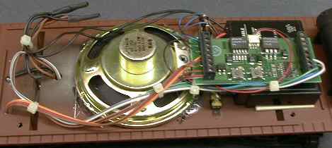
Take a meter and check for continuity between pin 2 and the - battery plug terminal, and pin 4 and the + battery plug terminal to confirm they are in fact the same. I remember doing this years ago, but didn't remember which pins. Greg's site discusses this and it is often easier to use the pins rather than dealing with the battery plug, which often breaks when the plug is removed.

As I said before, some regulators put out nothing until they see a certain voltage, but it seemed a bit lower (~12-13 volts).

The diode between the caps and Sierra in the latest sketch keeps the 7V produced by the Sierra board from feeding into the caps. The diode between the caps and buck/boost keep the caps from possibly backfeeding into the Buck/boost and taking this charge from the Sierra's idle time after shut-down. (BTW, we can still use the relay to conserve the voltage in the caps after shut-down.) I think that the Sierra will simply "see" which ever voltage is higher, so long as they are of the same polarity. It will not see the sum of the two voltages.

You can confirm this by running a train between two blocks on different dc power packs, where one block has a higher voltage, and when the train crosses blocks and sees both power packs simultaneously, it defers to the speed of the higher voltage, and not the sum of the voltages.

Again, Greg should be able to confirm this, or at least set us straight.
 
toddalin: It is a multi layered circuit board so visual inspection shows nothing. Did the meter tests you described. With a wire wound meter (Simpson) wasn't able to see any resistance between the points you mentioned, but with a digital I got bouncing results as if something was attempting to activate. Taking into consideration that an inactive solid state circuit may not show anything I did one more test. Attached a 6V battery (same technology) to the Battery input plug (6.42V) and read the same 6.42V between pins 2 & 4. Also consider that I am not using the lamp feature and did not activate the volume feature. I am willing to take the plunge and assemble the circuit as you describe with one difference, instead of using points 2 & 4 am going to use the battery inputs as Sierra designed. Just as a cautionary measure incase something else is involved that I couldn't see with the meters. Don't want to smoke the board as they are not supported any longer. Your thoughts?
 
61 - 80 of 139 Posts